Component selection
Film vs ceramic vs electrolytic vs tantalum
Ceramic - high frequency response due to lower inductance (therefore good HF filtering bypass incoming and outgoing noise), non-polar
Electrolytics - low cost, effective at low frequency, large capacitance, lifetime goes down and depends on temperature and voltage (therefore stick to ceramics for anolog filters), polarised
Interesting note: An electrolytic capacitor relies on an oxidisation layer as an insulator so capacitance will drift more over time if it run at low voltage
Tantalum - light, small, precise, higher cost
Film - linear characteristics (voltage-temperature-capacitance)
Selecting voltage rating for capacitors
Multiply voltage by 4/3 or 3/2 (electrolytic caps) and up to 2 (ceramic caps)
Eagle
- Eagle PCB tutorials by Ilya Mikhelson: Layout part 1, part 2
- Keep your components in one library: Custom library, Add 3D models to the library
- Manufacturer specifications: Design Rules files for OSHPARK, Cutouts, Drill specs
- Arduino shield template for Eagle from Adafruit library: ARDUINOR3 -> ARDUINOR3-BPLACE
- Footprints and 3D model collections: SnapEDA, Ultra Librarian, SamacSys on Mouser
- Change PCB color: Board view -> Manufacturing -> Configure Preview -> Copper Color / Soldermask Color
Cheatsheet
- create schematics document in Eagle
- Edit -> Add... -> Scroll down to frames, Choose LETTER_L
- If silkscreen and soldermask colors are swapped in Fusion 360, then check silkscreen contours outside of the board. Also measurements are not allowed
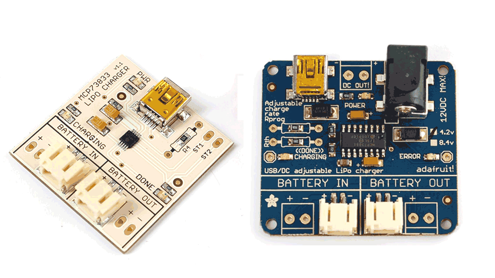
PCB design checklist (example):
- Rounded edges
- Copper-plated mounting holes
- Components aligned in a grid (vs. haphazard)
- Actually centered aligned everything
- No sharp corners on the traces
- Non-standard pcb color
Fusion 360
- Change PCB color: go back to Eagle
KiCAD
- Smooth traces in Melting Kicad
SMD Package Types
| SMD Package Type | Dimensions (mm) | Dimensions (inches) |
|---|---|---|
| 2920 | 7.4 x 5.1 | 0.29 x 0.20 |
| 2512 | 6.3 x 3.2 | 0.25 x 0.125 |
| 2010 | 5.0 x 2.5 | 0.20 x 0.10 |
| 1825 | 4.5 x 6.4 | 0.18 x 0.25 |
| 1812 | 4.6 x 3.0 | 0.18 x 0.125 |
| 1806 | 4.5 x 1.6 | 0.18 x 0.06 |
| 1210 | 3.2 x 2.5 | 0.125 x 0.10 |
| 1206 | 3.0 x 1.5 | 0.12 x 0.06 |
| 0805 | 2.0 x 1.3 | 0.08 x 0.05 |
| 0603 | 1.5 x 0.8 | 0.06 x 0.03 |
| 0402 | 1.0 x 0.5 | 0.04 x 0.02 |
| 0201 | 0.6 x 0.3 | 0.02 x 0.01 |
| 01005 | 0.4 x 0.2 | 0.016 x 0.008 |
Miscellaneous
The purpose of the bulk capacitor is to overcome the voltage drop caused by the inductive effects of PCB traces.
- connector and solder in options
- old school and SMD layout options

- LED indicators: battery ON, USB connected